Loop Antenna - Motor Control Part 1

I am starting to work on the automatic tuner for the magnetic loop antenna. I will implement the various functional blocks in the following order:
1. Motor control and homing
2. SWR measurement
3. Seeking algorithm to store history and tune quickly
Component Selection:
I am planning to use an STM32F401 mcu for this project. I chose this because I know it will have plenty of processing power, I have some NUCLEO eval boards already available, and I am familiar with the toolchain.
I am using a “SilentStepStick” stepper motor driver for the project. This is similar (and pin-compartible) with the Pololu stepper drivers based on the Allegro A4XXX chips. The SilentStepStick is based on the TMC2130 chip and has a few extra features exposed via a serial interface I think will be useful.
In particular, there is a feature called “stall detection” which detects when the load on the motor changes suddenly. This can be used to "home" a system without using mechanical endstops (this is what is done on the Prusa i3 MK3 printer). I intend to use the stall detection to “home” the variable capacitor on startup. The variable capacitor is a multi-turn capacitor with a hard stop on one end of the rotation. It would be difficult to home without the Stepstick because it is difficult to determine which turn of the multi-turn adjustment is the final turn. With the stall detection feature, I can turn the motor in one direction until the adjustment screw bottoms out and detect the point at which the stall occurs. That point will become the home position to allow positional data to be compared between power cycles. I will need to characterize this to see how repeatable it is, but based on my experiences with the Prusa i3 printer, I think it will be consistent enough.
The SilentStepSticks are available and in stock regularly at Digikey. Incidentally, they make a nice upgrade for your 3D printer and they do, as their name implies, make the stepper motors much quieter.
Initial Motor Driver Prototype:
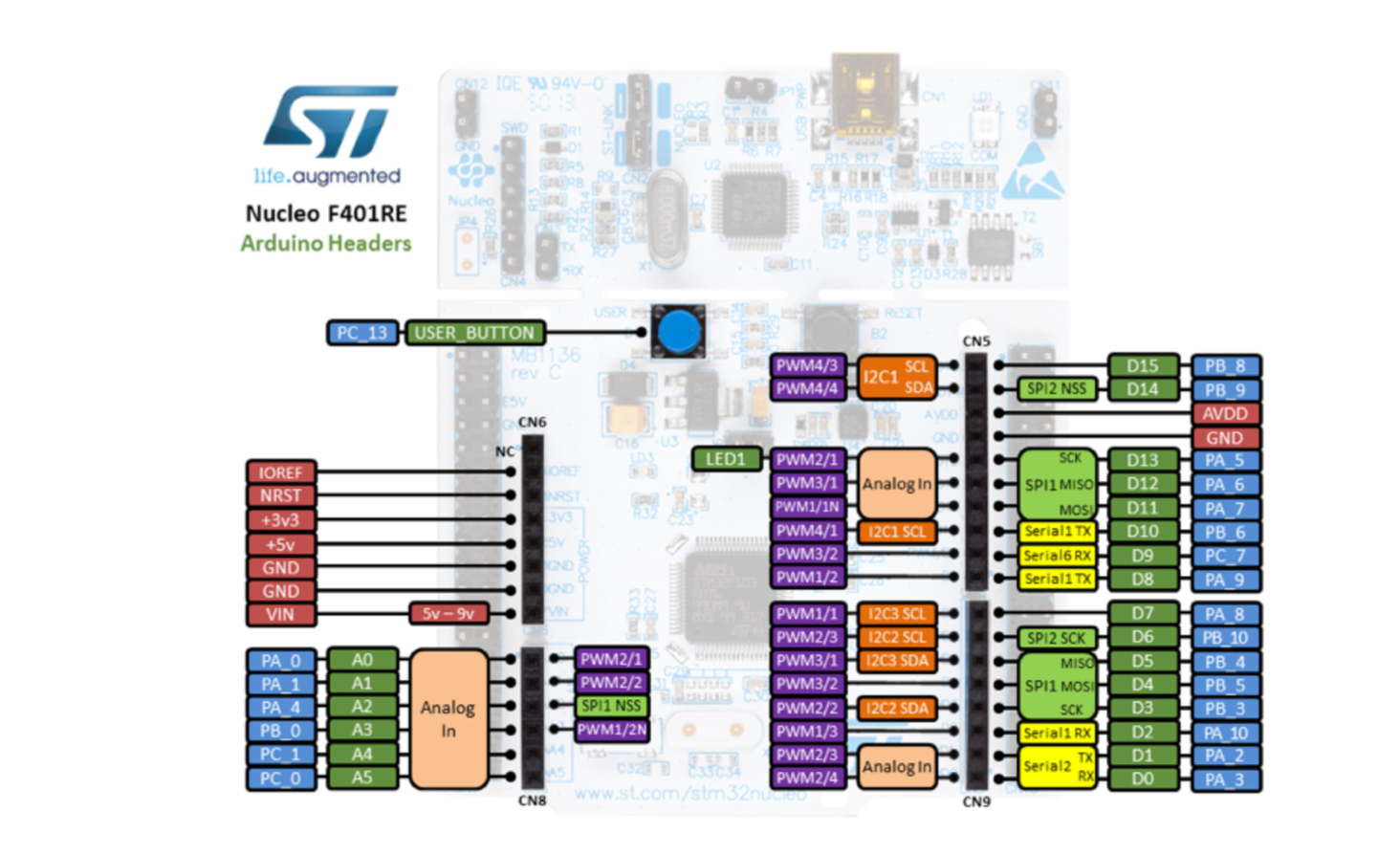
As a first step, I want to hook up the stepstick driver to a NUCLEO-F401RE eval board and get some basic motor operation. I am using STM32CubeMx to create the initial configuration for the project. The software has some pre-configured options for the various NUCLEO boards, so it makes it very quick to get a project started.
I am using the following configuration options in STM32CubeMX:
- SPI1 configured as full-duplex master with clock polarity high. Using Pins PA5 (SCK), PA6 (MISO), PA7 (MOSI) I had to remove the GPIO output functionality of PA5 since it appears to be connected to the green LED on the board.
- PB9 setup as a GPIO open-drain output with pullup enabled. I am naming this "MOTOR_CS". I will use it as a software-controlled CS pin.
- Enabled FreeRTOS
- Set PA4 to GPIO Output and named it "MOTOR_EN"
- Set PA8,9 to GPIO Outputs and named them "MOTOR_STEP" and "MOTOR_DIR" respectively.
- Set PA0 and PA1 as analog inputs (one or both of these will be used to measure the forward and reflected power going to the antenna).
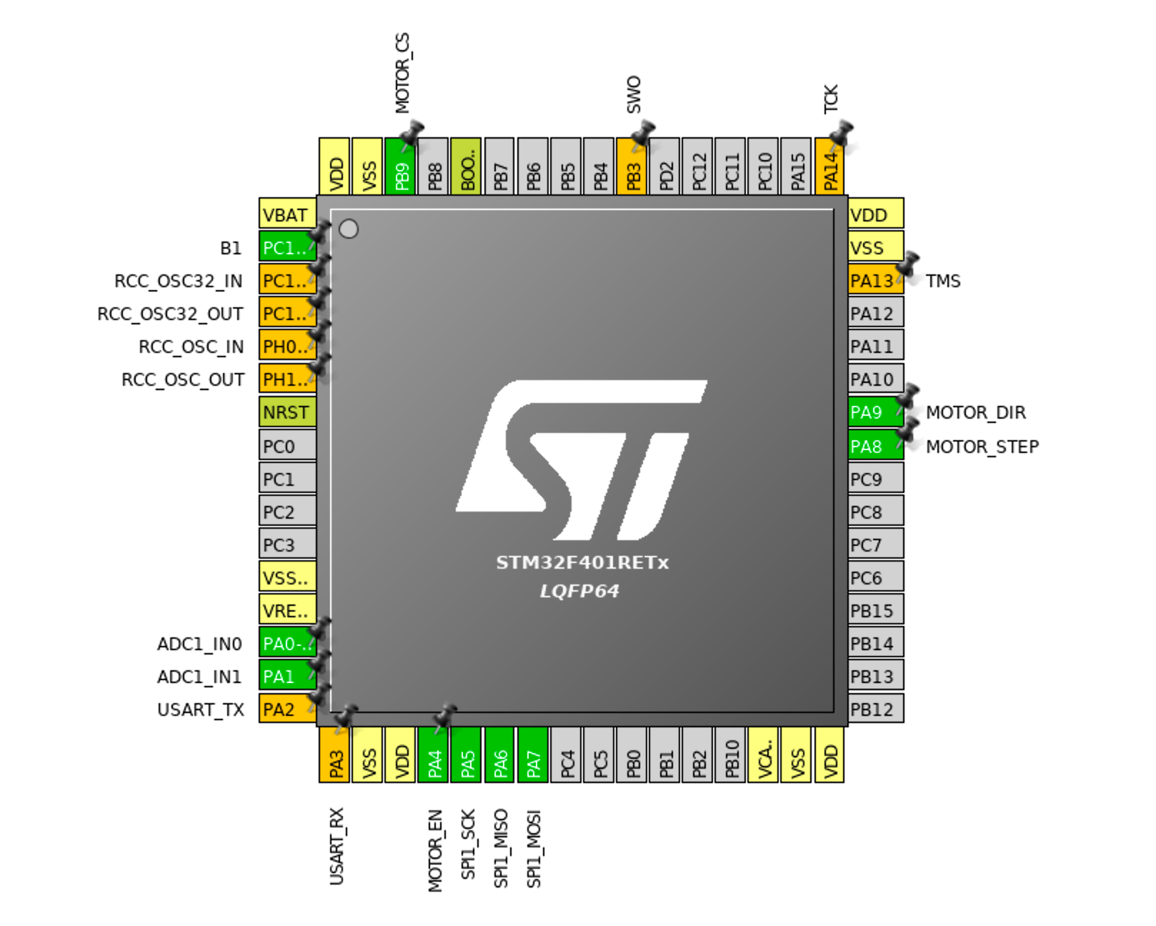
This is what the GPIO assignments look like in CubeMx:
I selected Acronis TrueStudio as the destination, and generated the source code using STM32CubeMX. As usual, I have to delete the "Drivers" and "Middlewares" folders from the Truestudio IDE and let them automatically re-populate (before that I get a bunch of errors bringing in various libraries). After that, the project builds and the STLink debugger works out of the box.
I need to be able to delay the processor for a few uS at a time to control the timing pulses of the stepper motor. I am using some of the code from this article to do so: https://www.carminenoviello.com/2015/09/04/precisely-measure-microseconds-stm32/
After building, I setup the motor_dir and motor_step pins to drive the motor back and forth 1000 steps in a loop. I wired up the SilentStepStick on a breadboard and attached the stepper motor. I'm using my workbench 13.8v power supply for the motor supply. There is a solder jumper on the SilentStepStick which, when connected, disables the SPI interface and allows the SPI pins to be used as configuration pins. I am using that for now in order to test the motor wiring and function without writing the SPI code. The pins can detect three states: open, GND, and VIO:
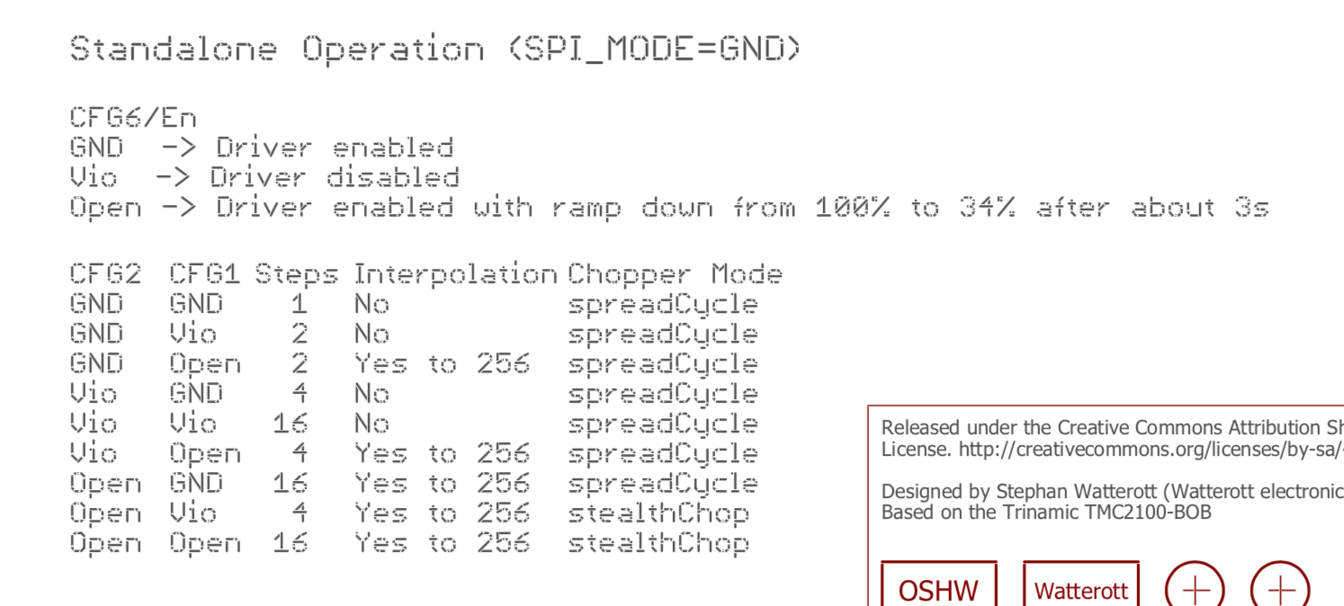
I am setting CFG1 to GND and CFG2 to Open. This should provide 16 uSteps with interpolation and "spreadCycle".
I turned on the power supply and started the program. At first, the motor started moving back and forth as expected. However, I quickly hit what seemed like thermal issues. The motor was stalling every second or so with an approx. 50% duty cycle. I tried adjusting the drive current using the potentiometer and reduced the VREF level from 1.1v to 500mV (the drive current is 0.71 * VREF), but the issue remained. Soon after this, I lost almost all function from the SilentStepStick. The only activity I could see is some brief movement after attaching or removing the "En" pin, followed by some choppiness, and then no movement. It seems like the driver is operating momentarily then hitting some kind of fault condition and disabling the output.
After reviewing the datasheet, I found the issue. The "CS" pin on the stepper driver becomes the "CFG3" pin when SPI mode is disabled. Here are the options for CFG3:
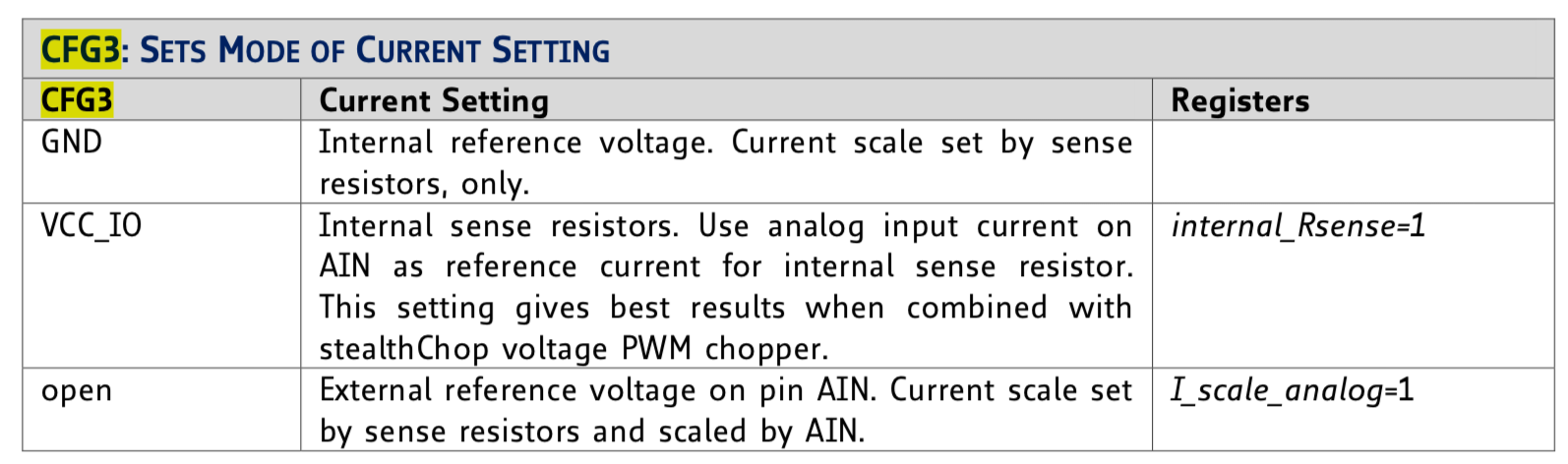
I had CFG3 connected to ground, which ignores the potentiometer and sets the current based on an internal reference. After removing the wire on the CS pin the stepper driver uses current proportional to the potentiometer voltage and the motor operation is smooth and continuous.
Ultimately, I was able to use the SilentStepStick without issue by connecting the SPI solder jumper to ground and then using the wiring connections below. Most of the pins can be left open. This configures the stepper driver for 16uStep operation (intepolated up to 256), with "spreadCycle" operation enabled, and current adjustment via the potentiometer. If you want a dumb, silent, stepper driver on a breadboard this will work well:
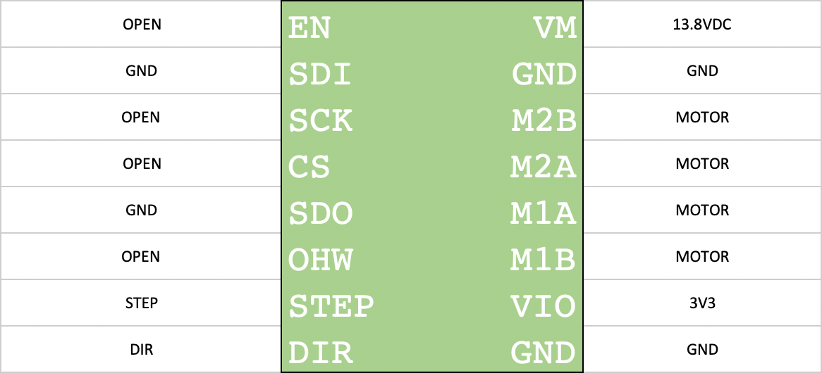
Now that I have confirmed the hardware is connected properly and the motor spins smoothly, the next step will be to enable SPI for configuration and stall detection.