Denmark: Amplifier Module
This post summarizes the build of an ICEpower-based 3-channel amplifier with DSP crossovers.
I am working on a new set of speakers with the project codename "Denmark". These speakers will be a pair of active (powered) 3-way speakers with subwoofers, woofer, and tweeter. They will include onboard DSP and are primarily designed to use digital optical inputs.
I will be writing a separate post about the acoustic design of the speakers. This post is about the electronics module that will go into each speaker.
The module is similar to something like the Hypex FA503 module available here. My DIY module has higher power output and headroom and otherwise a similar feature set. The form-factor of this module is also better suited for the speakers I am building because they will have drivers on both the front and back of the speaker.
I plan to use this amplifier in a 3-way system, but the same electronics can be used to build a 2.1 amplifier with DSP filtering and crossover.

Main Components
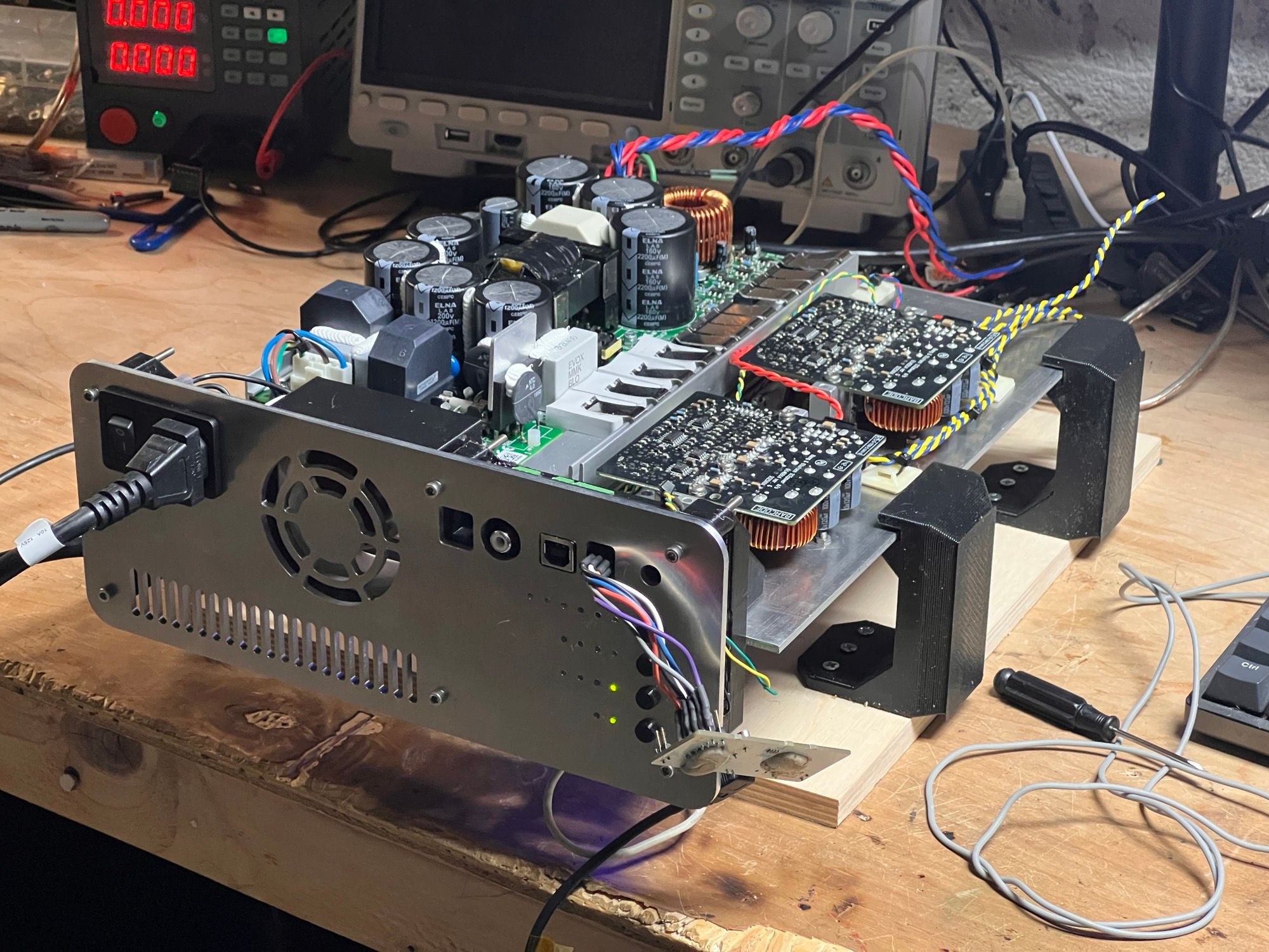
The amplifiers, MiniDSP, and power supply are all mounted on a 1/8" aluminum plate that serves as both a heatsink and a ground plane. All components are designed to be user-replaceable with connectors for all power and signal lines. No soldering iron is required to swap any components.
B&O ICEpower 1000ASP: PSU and Subwoofer Output
B&O ICEpower 500A: Woofer Output
B&O ICEpower 500A: Tweeter Output
Meanwell RD-35A: 12V/1A + 5V/4A Power Supply
MiniDSP 2x4HD: Optical Input, DSP tuning and crossovers
DIY PCB Controller: Thermal and power management and user interface

Controller Board
The ICEpower modules are designed so they can run standalone without an external controller. The power system will come up on its own in a clean and controlled manner. There are some limitations when using them this way:
- There is no overtemp monitoring on the 500A modules
- The amplifiers will remain on all the time and always consume quiescent power
- The output cannot be muted during DSP loading
The ICEpower modules have signals to control standby and mute. I designed a controller board to manage the amplifier power states, monitor temperature, control a fan, and manage the MiniDSP 2x4HD. Here is the block diagram showing the various functions of the PCB:

The MCU on the board is an STM32F401. The pin configuration in STM32CubeIDE is shown below. It looks like the chip is at full capacity, but if any additional functionality is required the LED outputs can be multiplexed to save some GPIOs. So far the design fits (just barely) with a single pin tied to each LED.

A pdf snapshot of the schematic is here:
The most recent schematic, BOM, and board files can be found on Github.
User Interface
Below is the user interface mockup I used when designing the PCB. There are 16 LEDs arranged into four banks. The board has five momentary push buttons.

LED Outputs
Status LEDs
Power: always on if the MCU is running.
Standby: turns on if the amplifiers are in the standby state
DSP:
One of these LEDs is lit at a time. This indicates which of the four DSP modes the MiniDSP has loaded.
Monitors:
Each of the monitors will show the state of a fault in realtime. For instance, if the fan is obstructed the "Fan Slow" monitor will illuminate. Once the fan is back to the nominal RPM range the LED will turn off again.
Faults:
The fault LEDs illuminate the first time a fault occurs and must be cleared manually.
Button Inputs
Standby
This button toggles standby. When the amplifier is in standby mode the fan is turned off, the monitors are paused, and the amplifiers are placed into standby mode.
DSP Mode
Each time the DSP Mode button is pushed the next DSP mode is loaded into the MiniDSP. The PCB emulates an IR transmitter and sends the command to the MiniDSP to change to a specific configuration. The DSP state is stored in nonvolatile memory and the DSP state is applied on powerup so the controller and the MiniDSP should remain in sync as long as the IR transmitter communication is robust.
Adjust Display
This button is used to "mute" banks of LEDs. For instance, the monitor and fault LEDs can be disabled during day-to-day operation of the amplifier.
Clear Faults
Immediately clear all of the fault LEDs.
Source Toggle
Switch between optical and analog input sources.
Here is a video showing a demo of the user interface:
IR Control of MiniDSP
The MiniDSP 2x4HD does not enable a digital interface to adjust the DSP settings. There is no ability to change biquad coefficients, gains, or other DSP parameters using SPI, I2C, or any other wired interface. The onboard processor is capable of this, but from what I've read on their support forums, it seems that MiniDSP understandably thinks that enabling this functionality would put a burden on their support and engineering teams.
The MiniDSP does support an IR remote and a set of four pre-configured DSP configurations. The IR remote currently shipping with the 2x4HD has a dedicated button for each of the four DSP modes.
The controller PCB on the Denmark amplifier has a driver circuit for an infrared LED and emulates a remote to select a DSP configuration on the MiniDSP.

The MiniDSP 2x4HD has a "learn" function. The denmark controller firmware uses arbitrary commands that are recorded/learned using the MiniDSP PC software. Through some trial and error, I found that the MiniDSP worked well receiving IR messages formatted in the NEC protocol described here. It was unable to learn some other protocols I tried.

I found that the learn function worked best after sending the same sequence twice in a row. If you uncomment the line: "//#define IR_TRAINING" in infrared.h the function ""train_minidsp()" will be compiled into the executable in infrared.c. Stepping through this function with a debugger will allow you to train the MiniDSP to listen to the controller.
It should be possible to emulate the native commands of the MiniDSP remote directly and avoid the requirement of training. I don't have one of the remotes so I can't verify it myself. If you have details about the protocol and commands used by the MiniDSP remote please send me an email and let me know so I can update the firmware.
Mechanical Construction
The design is modeled in Fusion 360:

The back panel is CNC milled out of a 1/8" aluminum sheet. It could also be cut out of a sheet of acrylic or 3D-printed – although I would recommend some minor modifications to better secure the IEC connector if using those materials.

The PCB is sandwiched between a large 3D-printed plastic piece and a thin 3D-printed spacer.

The 3D-printed spacer holds the light pipes for the LEDs. These route the light from each of the 0805 surface mount LEDs to the surface of the aluminum back plate. The light pipes themselves are segments of 1.75mm transparent PETG printer filament. This method works very well – the LEDs could be a few inches from the perimeter of the enclosure and the pipes would still work effectively. I will use this technique on other designs in the future.


Without the light pipes the LEDs have a very limited viewing angle. The LEDs are recessed far enough back that they are visible only when viewing from directly behind the amplifier. The illumination of the LEDs is also much more even with the light pipes.

Firmware
The firmware for the controller board is available on Github. If I make any future changes, I'll keep the board files and firmware images in sync. Since this is a work-in-progress, please feel free to send me an email if you are planning to assembly your own amplifier. I may have further improved the design or added features that aren't described on this post.
Many of the tasks and functions are simple enough to follow by code/comments. Here is the powerup and standby diagram I used when writing the firmware:

Wiring Diagram
Here is the wiring diagram I created when wiring up the module. All of the colors match the wired connectors I purchased with my ICEpower modules, but I recommend confirming the pointouts with the module datasheets.

Next Steps
I will be sanding the aluminum back panel with a subtle brushed finished and then anodizing it black.
I also plan to spend some more time refining the button design. The buttons feel good now, but there is some variability in the feeling of each button based on some tolerance issues with the 3D printed parts. I plan to re-design the button caps so that they 3D-print more accurately.
Conclusion
Please reach out if you have any questions or would like any additional design resources. I have a lot of additional documentation and notes that I can share with a bit of cleanup. My goal is to enable others to be able to reproduce projects like this, so please don't hesitate to ask. I consider this entire design open-source and I'm happy to share any design collateral.