Loop Antenna - Assembly and First Test
Today I finished assembling the loop antenna and ran some tests on it for the first time. The results look great so far and after this I'll be ready to put it on the air.
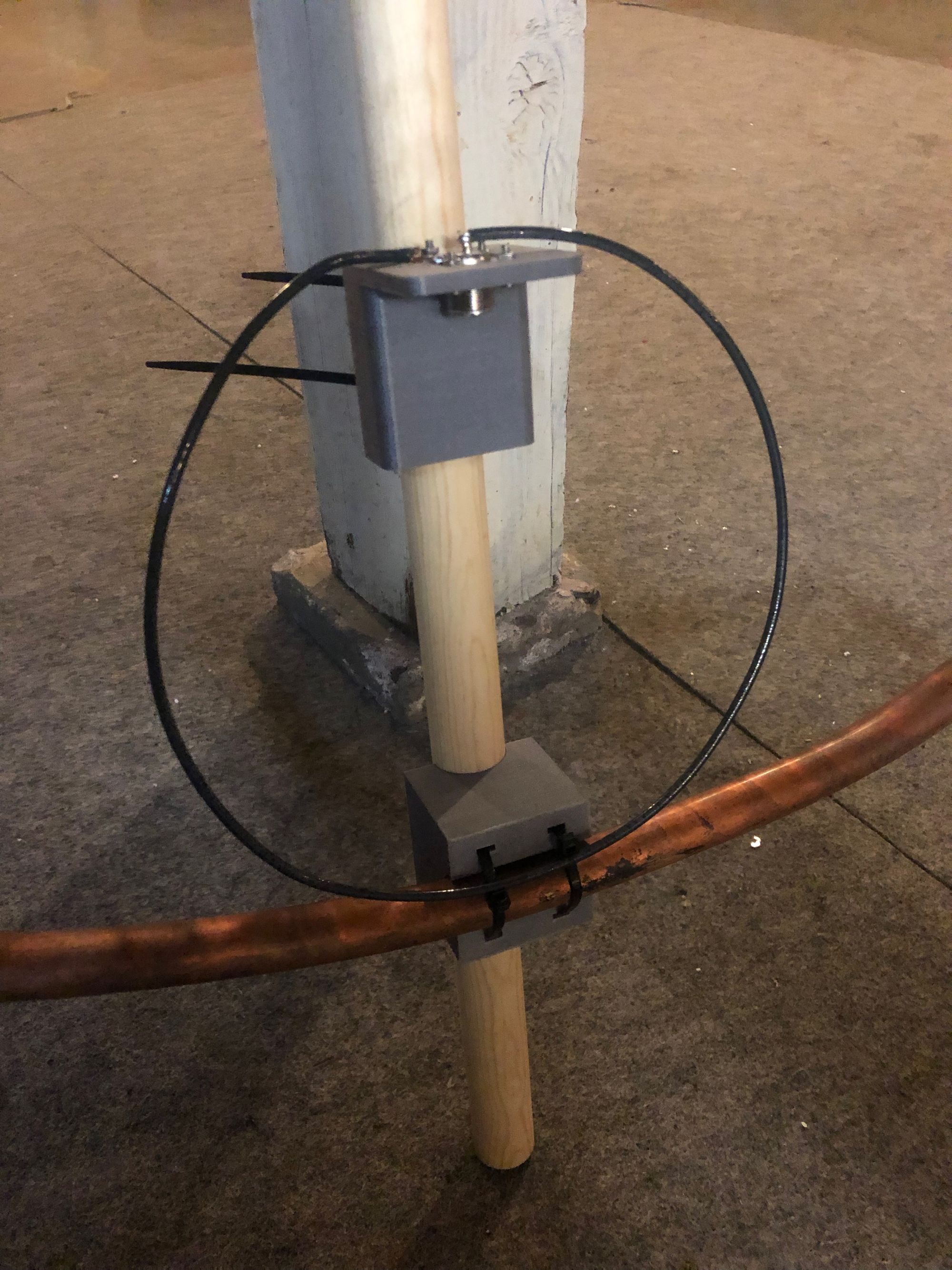
First, I screwed on the plastic clamp pieces to each ends of the copper loop:
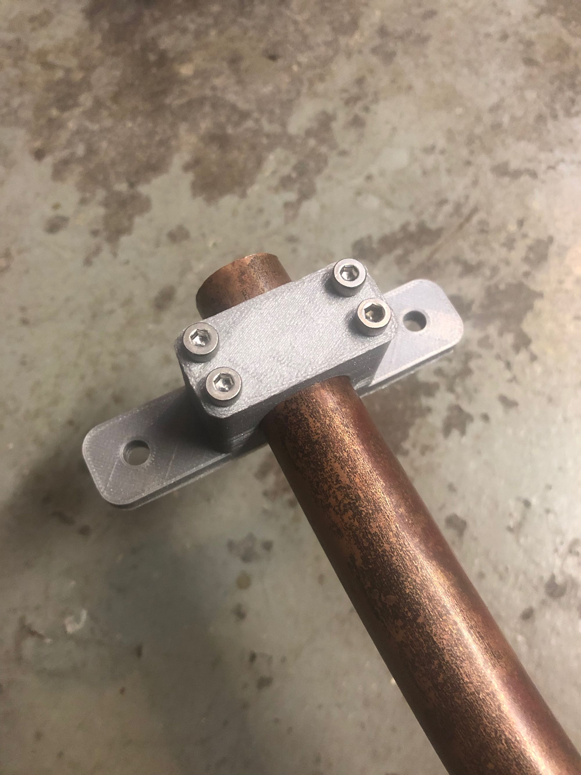
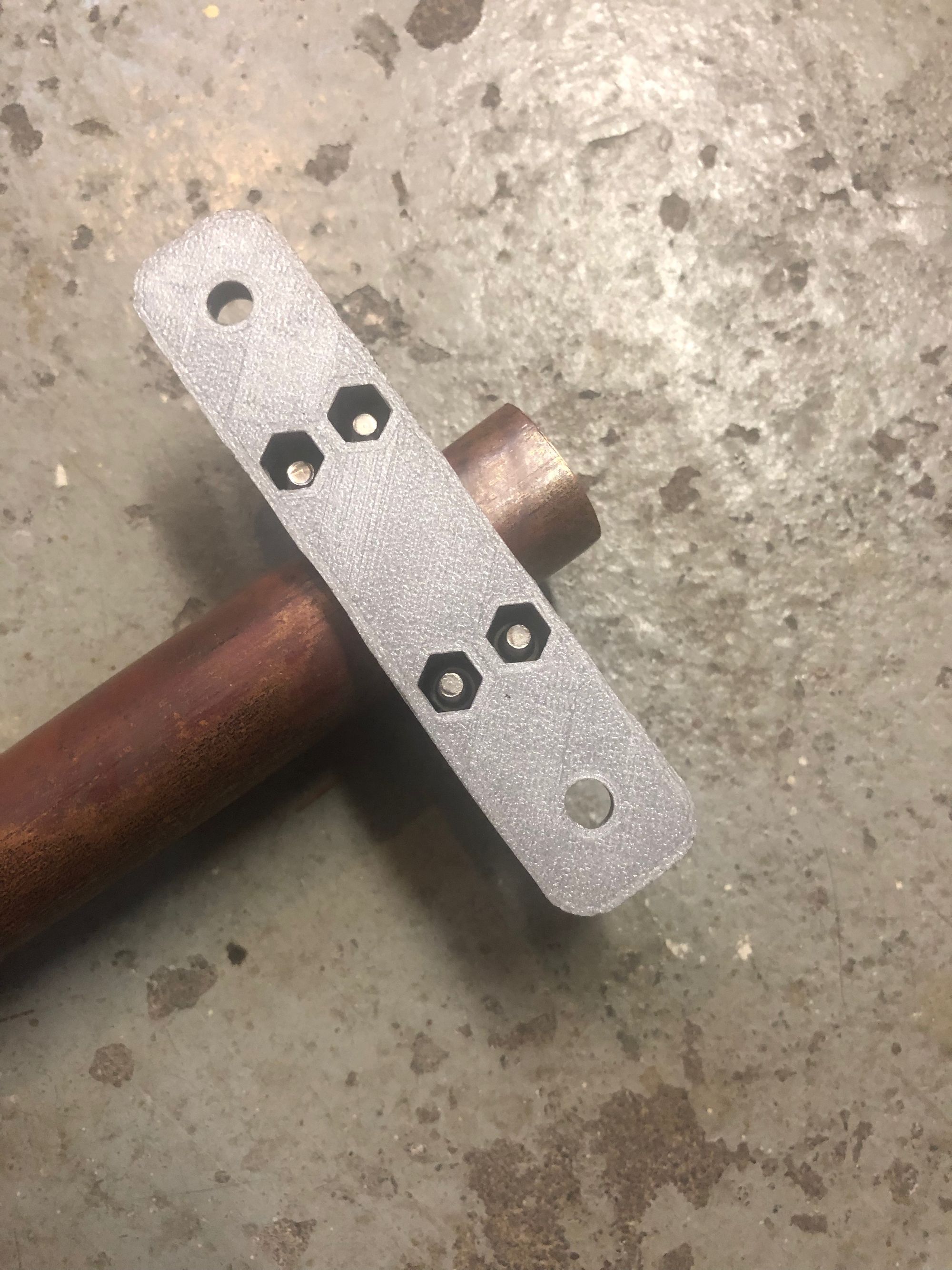
I bought some 6 awg copper crimps at the automotive store. I folded the end of some 10 awg wire in half and hammered the clamp onto the wire to make a solid connection. A hole just large enough for an M5 screw is drilled into the copper pipe and the clamp is firmly attached.
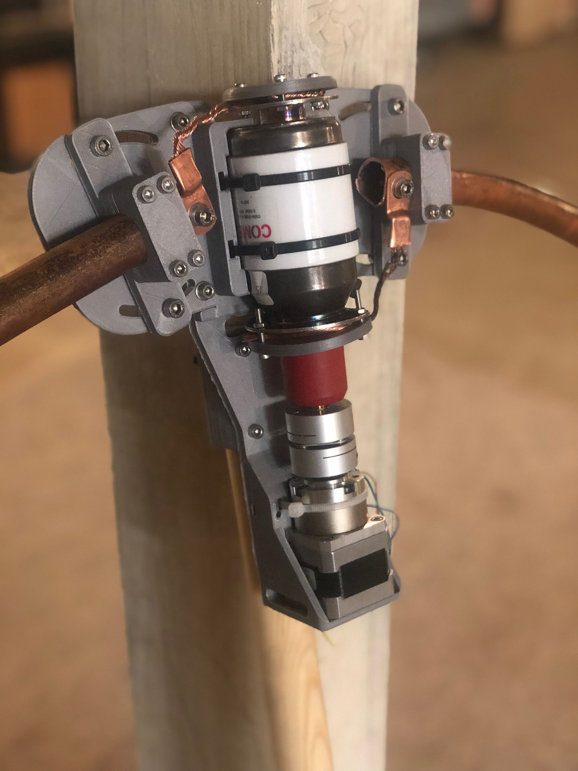
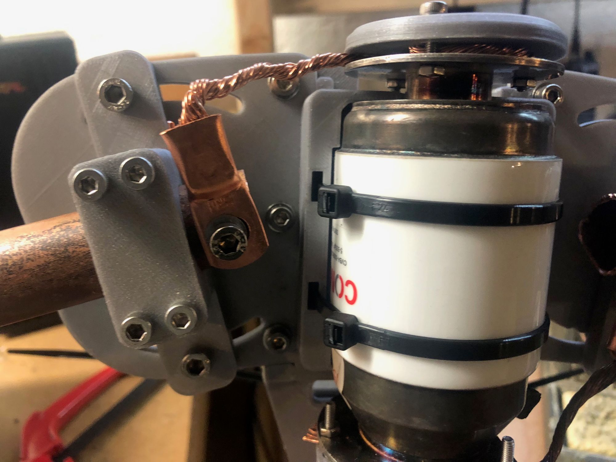
The 10awg copper wire is sandwiched between the metal plate of the capacitor and a plastic cover piece. Three m3x12 screws are used to clamp the wire firmly and maintain a solid connection.
The antenna is designed to be mounted on a 1.25" wooden dowel. I purchased two 48" wooden dowels from harbor freight and I plan to 3D-print a plastic butt joint to connect the two. I still need to decide what I will use as a base when the antenna is outside.
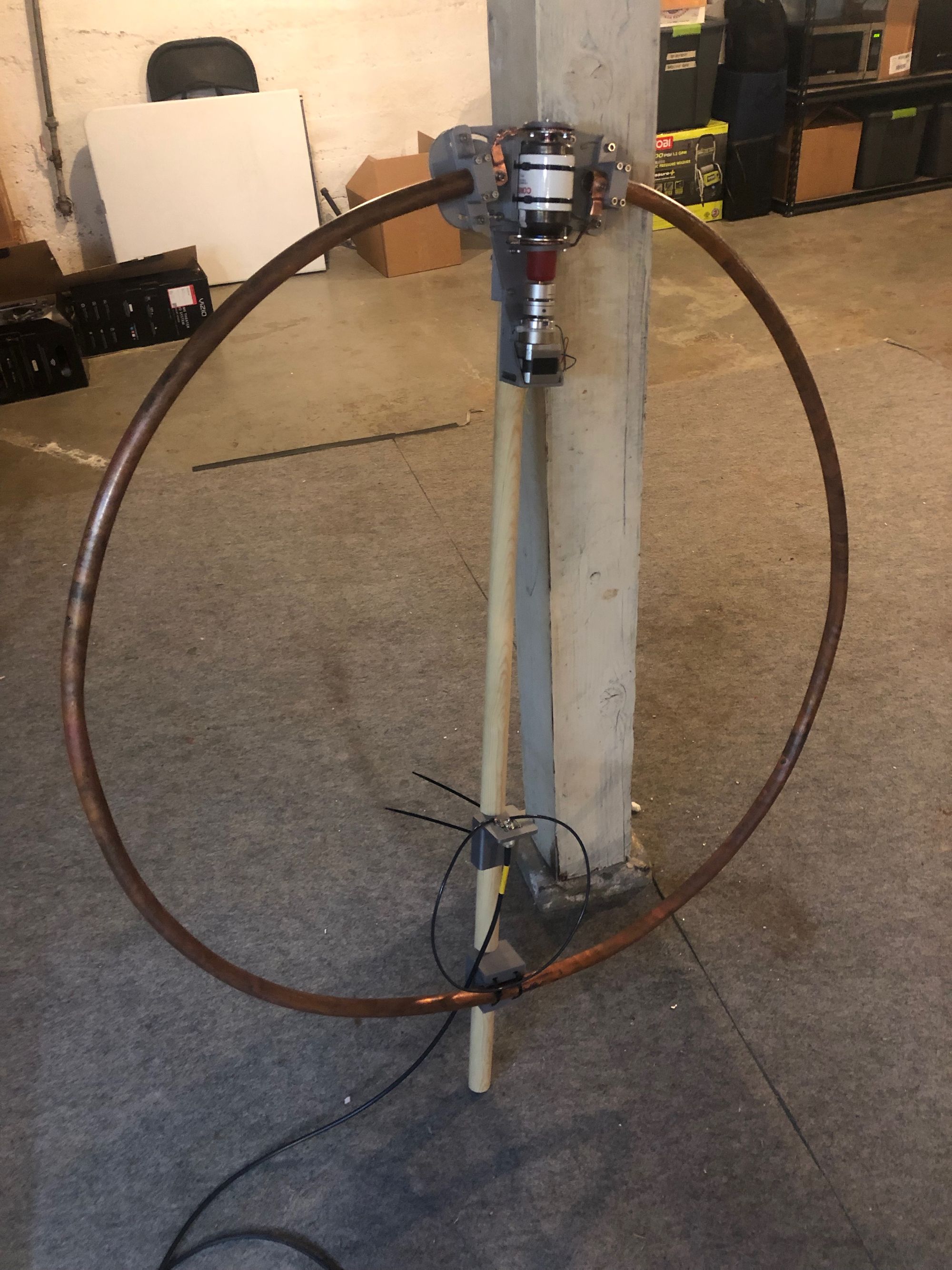
The driven loop is made up of about 2ft of 10awg wire with the insulation intact.
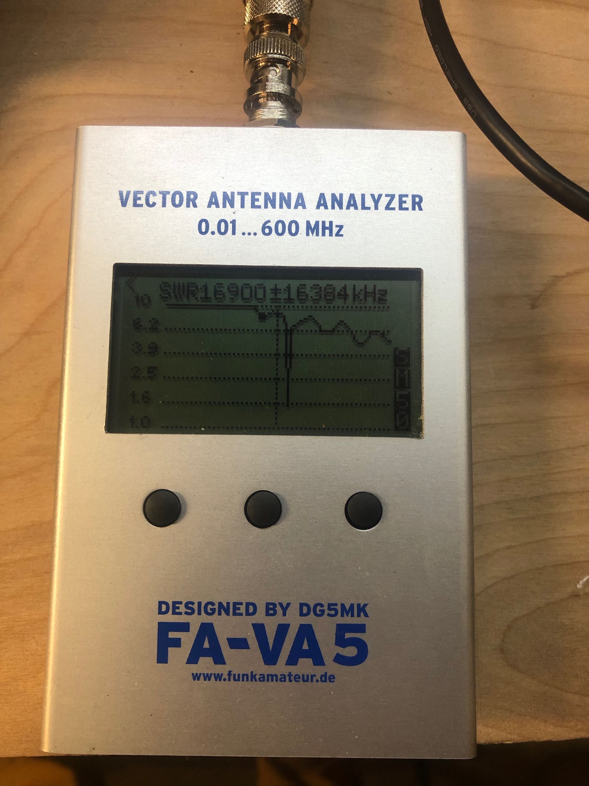
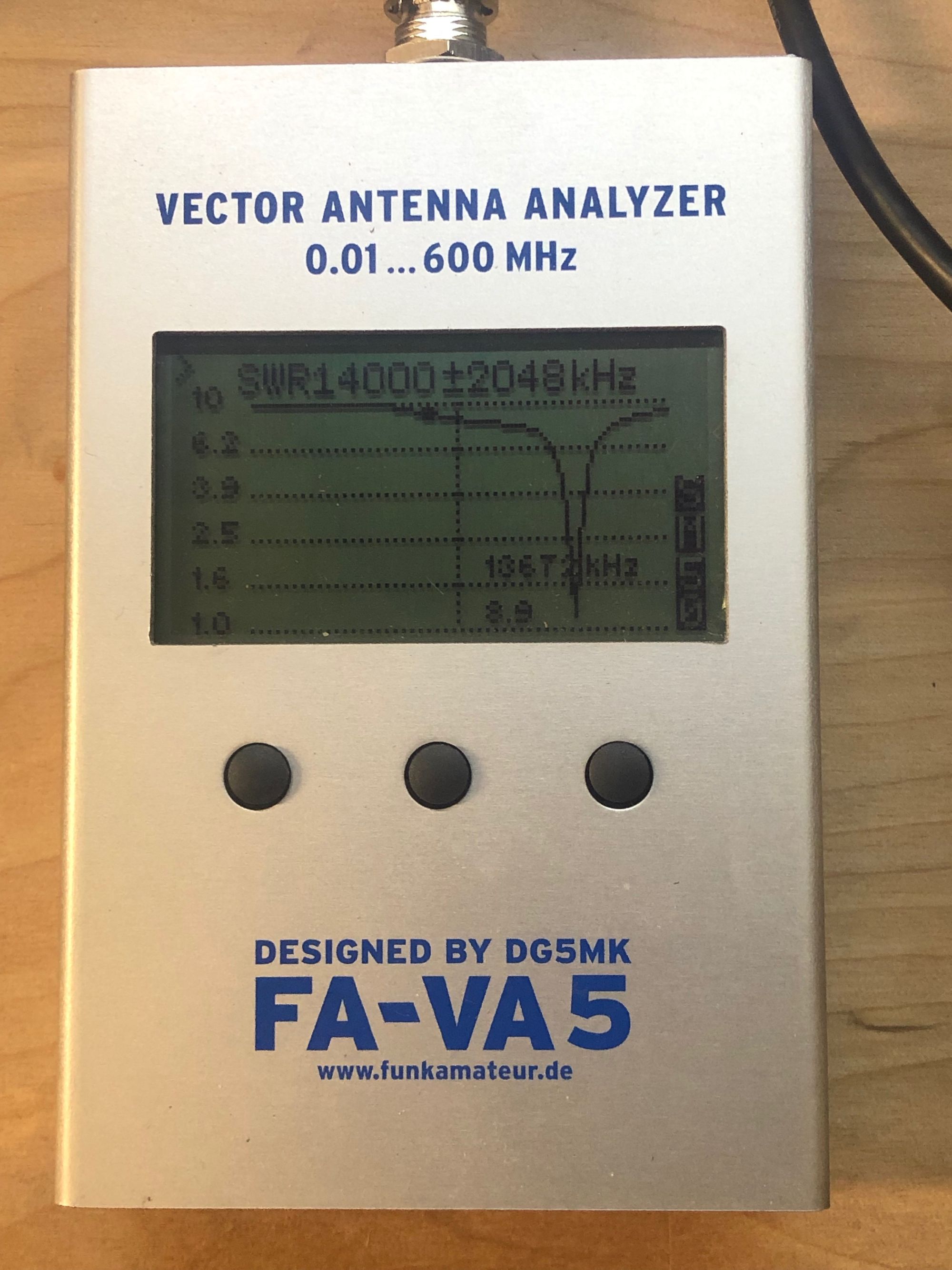
Without adjusting the capacitor at all (it is somewhere between the two extremes of the tuning range) I attached my FA-VA5 antenna analyzer to take some SWR sweep measurements. The first sweep looked encouraging – there is clearly a strong, narrow resonance at a specific frequency where the SWR falls to below 1.5.
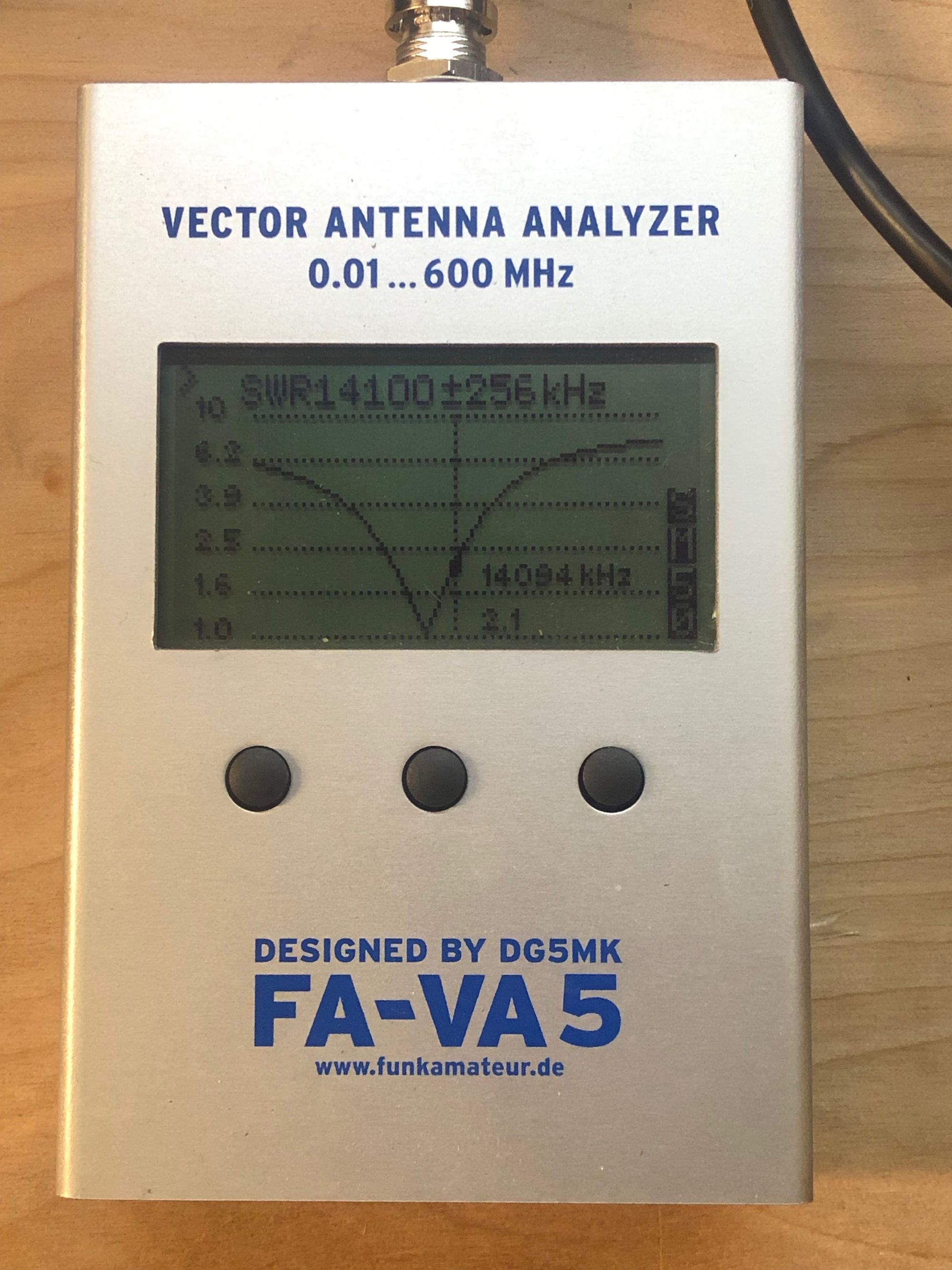
After adjusting the capacitor some, I was able to "tune" the antenna for ~14MHz. The tuning adjustment is very sensitive! A quarter-turn of the capacitor can have a significant effect on tuning frequency. I think the gear reduction of the stepper motor may end up being helpful. I am really encouraged to see that the SWR goes down to a 1.0 – hopefully that means I'll get some good results from the antenna on the air.
Next steps are to try out the antenna on the air, and start working on the auto tuner circuit.