Ham Radio Loop Antenna
Intro to my Loop Antenna Design
I've been experimenting with various antenna installations around my house for use with ham radio. Propogation is poor right now as we are at the bottom of the sun-spot cycle, so it is important to have an effective/efficient antenna if you want to be heard.
One type of antenna I've run across which seems interesting/unique is the magnetic loop antenna. These are typically constructed with a loop of conducting material formed so that the two ends of the loop are almost touching. In the space between the two ends a variable capacitor is placed and tuned to resonate at a specific frequency.

Magnetic loops are typically extremely high Q devices that are tuned for a very narrow range. This narrow operating range means the antenna naturally provides some amount of selectivity, but it comes at the cost of needing frequent re-tuning. Changing frequency by even 2-3kHz can shift you out of the operating band of the antenna.
I want my loop antenna to work well on 20m, and for conveience I'd like to assemble it from copper piping (0.75" OD, 10 feet long). I also want to be able to operate up to 100W. I put those parameters into the calculator here and got the following results:
Antenna efficiency: 60% (-2.2 dB below 100%)
Antenna bandwidth: 18.9 kHz
Tuning Capacitance: 62 pF
Capacitor voltage: 3,687 volts RMS
Resonant circulating current: 20.1 A
Radiation resistance: 0.074 ohms
Loss Resistance: 0.050 ohms
Inductance: 2.08 microhenrys
Inductive Reactance: 183 ohms
Quality Factor (Q): 742
Distributed capacity: 8 pF
See the capacitor voltage of almost 4kV? With an air-core capacitor it is likely that the high voltage will cause arcing across the fins of the capacitor. There are methods to avoid this (increase spacing, submerge in oil), but a common approach is to use a vacuum variable capacitor.
I got the following model from ebay: Comet CVBA-500BC:

This capacitor has a tuning range of 5-500pf, a max voltage of 5kV, and a peak operating current of 57A.
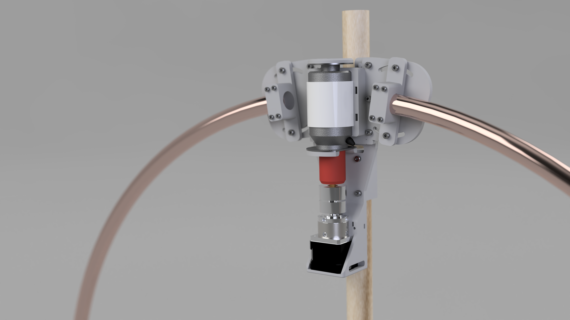
I designed and printed a plastic holder for the variable capacitor. I also added a geared stepper motor, mounting points for the copper pipe, and plastic pieces to mount the loop to a wooden dowel.
The printed pieces look like this:

The assembled antenna should look something like this render from Fusion360:

If you want to make any changes to the design or print it yourself, I am sharing the Fusion 360 project here: https://a360.co/2TtVUop.