Modifying the Air Popper
This page shows the process of modifying a Poppery II popcorn popper so that the motor and heater coils can be operated independently of each other. During the modification a thermistor is added to monitor the temperature of the coils and a thermocouple to monitor the chamber temperature.
Back to Intro.

This page shows the process of modifying a Poppery II popcorn popper so that the motor and heater coils can be operated independently of each other. During the modification a thermistor is added to monitor the temperature of the coils and a thermocouple is added to monitor the chamber temperature. The popper ends up with four pairs of wires ready to be connected to an external controller.
The first step is to open the air popper and check the connections to the fan and the heater coils.

The motor is a DC brushed motor rated for 20.5VDC and 1.78A.


The air popper has a simple and clever design with two heater coils. One coil (C2) is wired in series with the motor and is used to reduce the 120VAC from the wall output down to a voltage suitable for the motor. This divided voltage is rectified by a full-bridge rectifier soldered to the motor terminals. The other heating coil (C1) is wired in series with an onboard thermostat (F2) so that it cuts off when the thermostat reaches 150C. This provides some simple thermal regulation.
The thermostat is mounted on a fire-proof board covering the heating coil. It is situated below the heater and is blown on by the cold air intake. I've found that the temperature measured here is considerably lower than the air temperature inside of the chamber. I didn't measure the temperature in the chamber before I modified the air popper, but I suspect it reaches a steady state quite a bit higher than 150C.

I disconnected the rectifier from the fan motor and soldered two long directly to the fan terminals:

Next, I rewired the air popper so that coil C2 is connected in parallel with C1 and F2 without the motor in series. I also removed a small metal strip from the breaker F2 to prevent it from opening at 150C. After these modifications, the heater load is effectively C1 and C2 in parallel. I left the 216C fuse in place as a safety precaution, but it should never open and will need to be replaced if it does.
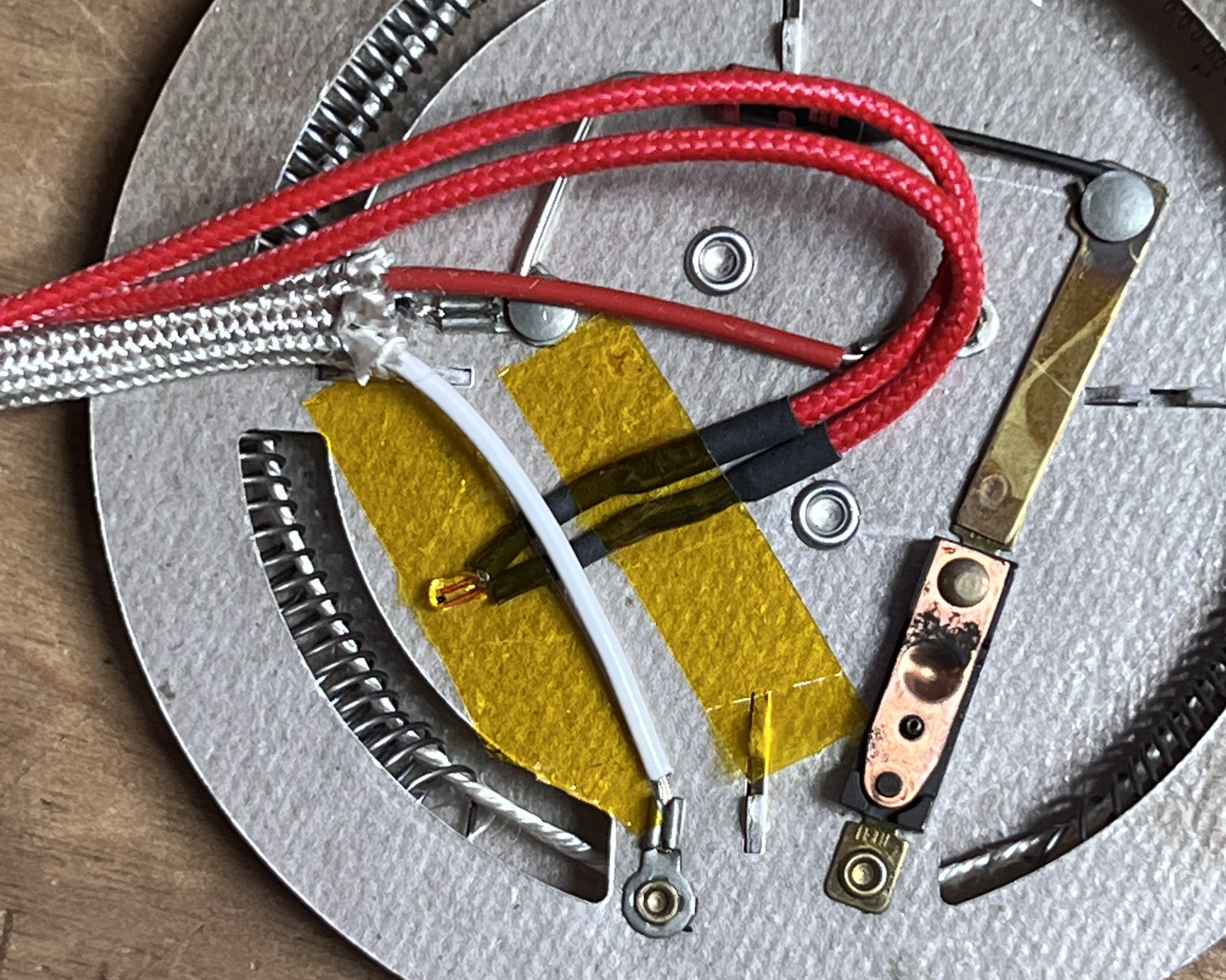
After making these modifications, I was concerned that the air popper coils may get too hot. I was particularly concerned about coil C2, which will consume up to an extra 50% power with the motor removed. I also want to know if the onboard temperature ever approaches 216C so I can disable the heater before blowing the thermal fuse. I added a thermistor to the board so I can monitor the temperature:

I used mechanical crimped connections to the thermistor since it is used in a high temperature environment and the airflow over this will also go across the coffee beans.

I added strain relief to the wires and routed them to the hole in the Poppery Housing.

And verified the fan functionality with a benchtop power supply:

After this initial modification, I opened the air popper again and drilled a small hole to attach a type-k thermocouple. I forgot to take pictures of this, but the placement can be seen below. The thermocouple is a friction fit into the metal chamber housing.

With the air popper modified, the next step is to build a control board to set the heater and fan appropriately for roasting coffee.
Next: Building the Control Board.