Loop Antenna Copper Jumpers
I am planning to machine some copper jumpers to go between the copper loop and the vacuum capacitor. These can be soldered (or brazed) to create a solid connection with very low resistance.
I've had the loop antenna on the air a few times and I'm very satisfied with the results. The follow items are remaining before I can call this project complete:
- Add copper jumper to lower the resistance between the copper tubing the the vacuum cap.
- Finish the software for homing the stepper and automatically adjusting the tuning for each of the bands.
- (Optional) - I may choose to weatherize the antenna for longterm outdoor use.
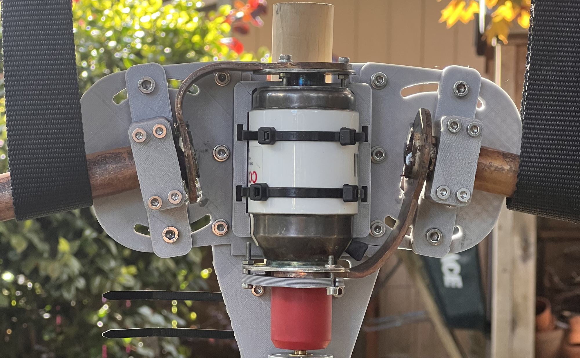
First, I am going to start by finishing the design mechanically. The antenna uses some stranded copper wire between the tubing and the variable capacitor. This is a limitation – I have noticed the efficiency of the antenna has decreased over time and it especially decreased when I accidentally left it out in the weather overnight. Over time I've been able to improve the efficiency again by re-positioning and re-tightening the stranded wire connection – I would prefer if that wasn't necessary.

I am planning to machine some copper jumpers to go between the copper loop and the vacuum capacitor. These can be soldered (or brazed) to create a solid connection with very low resistance.
First, I modelled up the brackets in Fusion 360:

I modelled these as solid objects and did not use any sheet metal features. I then used the solid models as a reference to re-create the models in 2D:

I generated toolpaths using the CAM functionality of Fusion 360 and cut the brackets out of some copper sheet using my benchtop mill:


I haven't cut much copper and the mill and the material was very gummy. It ended up cutting okay, but I had to spend some time removing a thick burr that formed on the edge of the part. I did a bit of sanding on the top and bottom surfaces and ended up with a couple of nice-looking parts:

Here is one of the jumpers at the end of the piping, ready for solder:

And here is the result after soldering. This was my first time soldering copper piping with a torch. The result is a bit ugly, but the connection is solid. I've since read that brazing may be a better approach to further lower resistance. I also let the torch heat up the body of the jumper in order to anneal it and make it more pliable for forming.

The round section of the copper jumper interfered with the plastic portion of my 3D print. I used an oscillating saw to cut away some of the material:

And then finally I mounted the jumpers in place. I'm happy with how the pieces lined up and contribute that to modelling everything ahead of time.

Here is a final image of the re-assembled antenna with copper jumpers in place:

And here is the SWR reading for 40M:

Next step is to finish developing the stepper driver code and get it into regular usage.
Done for now.