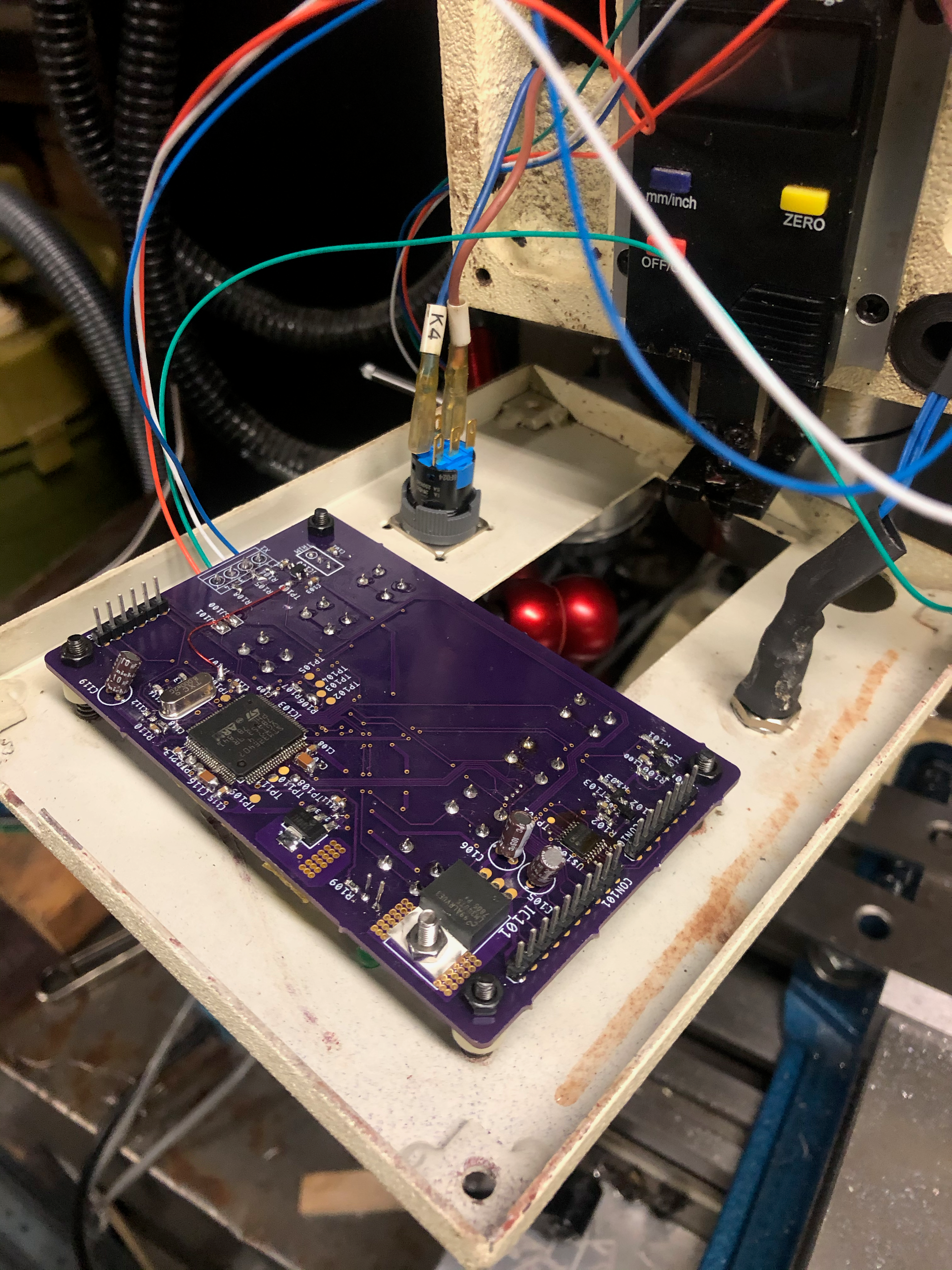
LCD Control Board for SX3 Mill
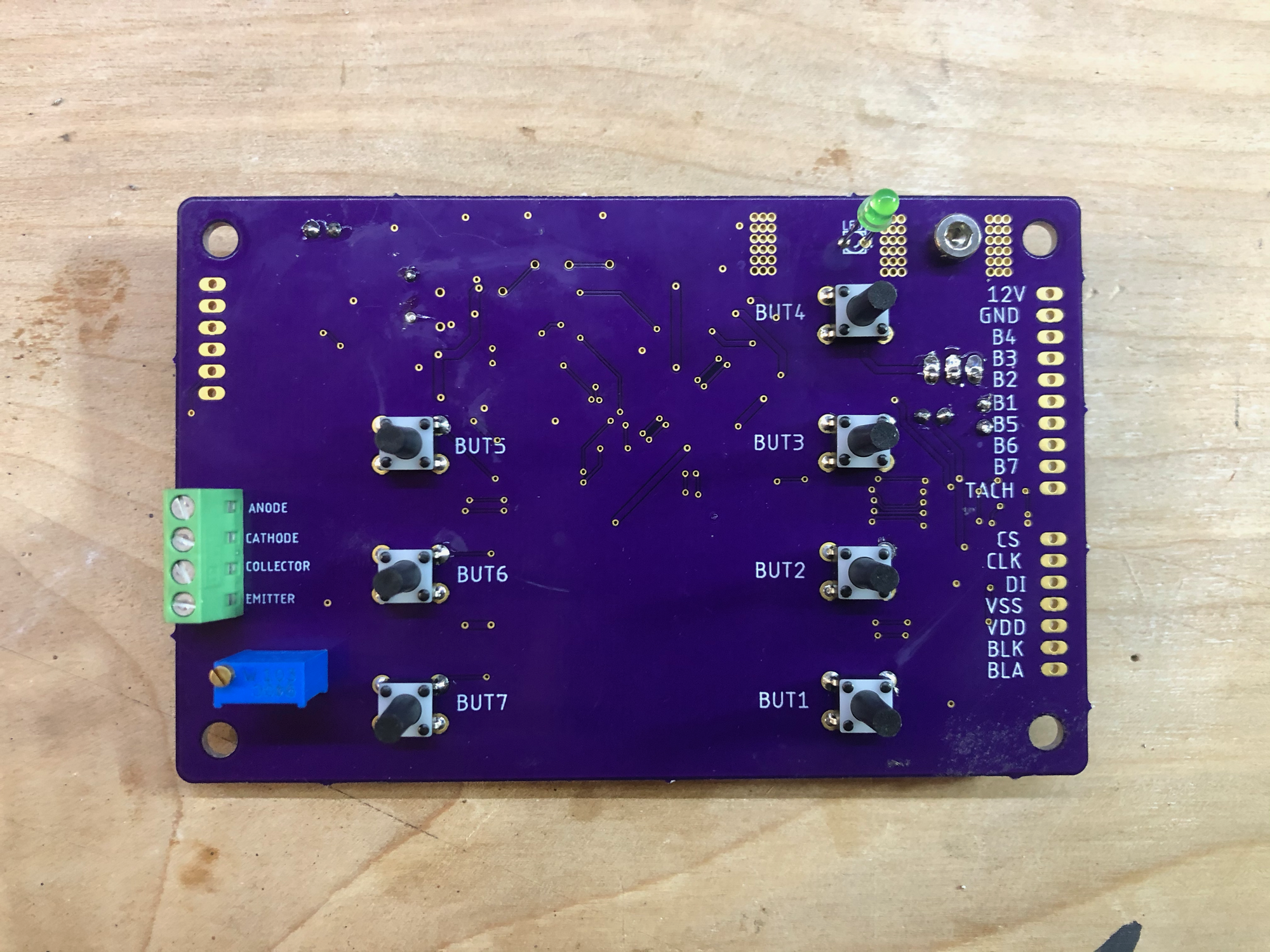
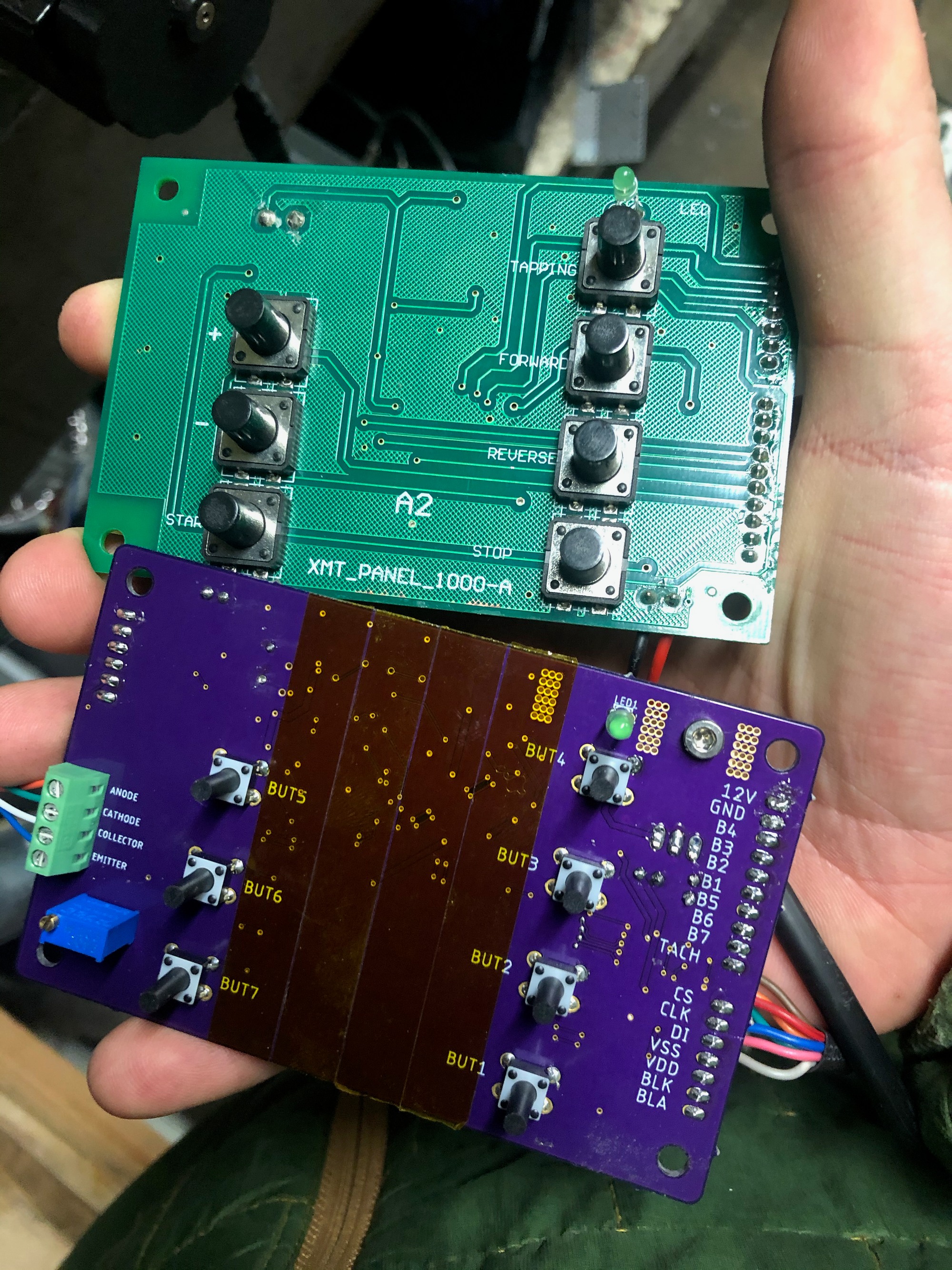
The LittleMachineShop control board replaces the button board built in to the mill, so when the spindle control board is connected the buttons and LCD built in to the mill are no longer functional. I designed a drop-in replacement for the button board to help add back some functionality.
For the last couple of years I've been working on converting my Shop Fox M1111 (SX3 variant) mill to CNC. I'm using a MESA 7i76e control board connected to my PC running LinuxCNC.
I recently bought the LittleMachineShop spindle control board so that I can control the spindle speed using a 10v analog output from my controller. This control board replaces the button board built in to the mill, so when the spindle control board is connected the buttons and LCD built in to the mill are no longer functional.
I designed a drop-in replacement for the button board to help add back some functionality.
Here is a video of the board installed into the Mill. Things are very messy, at the moment, so please forgive the wiring!
Spindle Tachometer:
The board has a screw terminal input for a IR reflective sensor. The output of the sensor is RC filtered and passed through a comparator with an open-collector output. The comparator output is connected to the MCU and also passed to an external connector so it be read back from LinuxCNC through the MESA controller.
Button Breakout:
The board has buttons in the same location as the original board. Each of these buttons is brought out to a 1x12 pin header which was originally used to communicate with the motor controller on the mill. Now these buttons can be easily wired as inputs to LinuxCNC for whatever functions I want to assign.
LCD Control:
The board has a connector for the LCD built in to the mill. I used a logic analyzer to figure out the serial protocol for controlling the LCD and implemented it in my firmware. Currently, the firmware reads the numbers of tachometer rotations in a 1 second period and multiplies this by 60 to display RPM. I will likely add some digital smoothing to find the right balance between responsiveness and resolution.
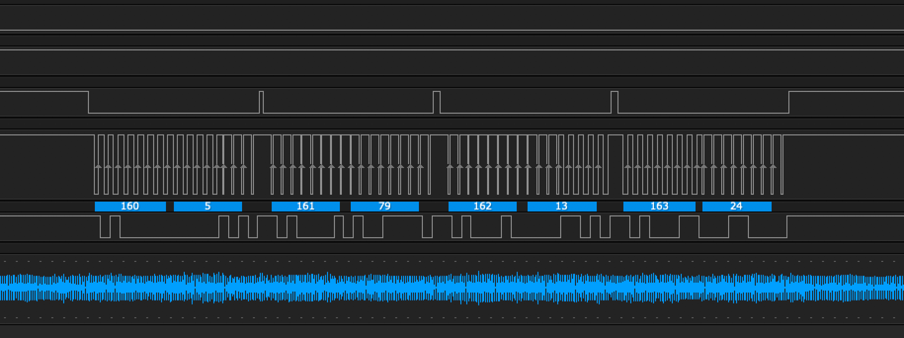
The LCD serial protocol is broken into two parts. On power up, the LCD will be unresponsive until a setup configuration is sent. I didn't spend any time trying to understand/decode this sequence – I just copied it exactly and saw the LCD come to life. The image below shows the startup sequence measured from the original board (top) and from my replacement board (bottom):
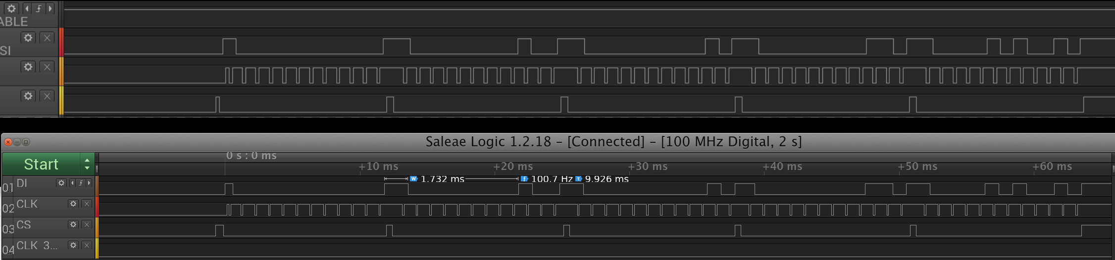
After initial configuration, the LCD control board can be sent a series of four 9-bit values to configure each of the digits. Here are some of the waveforms I recorded:
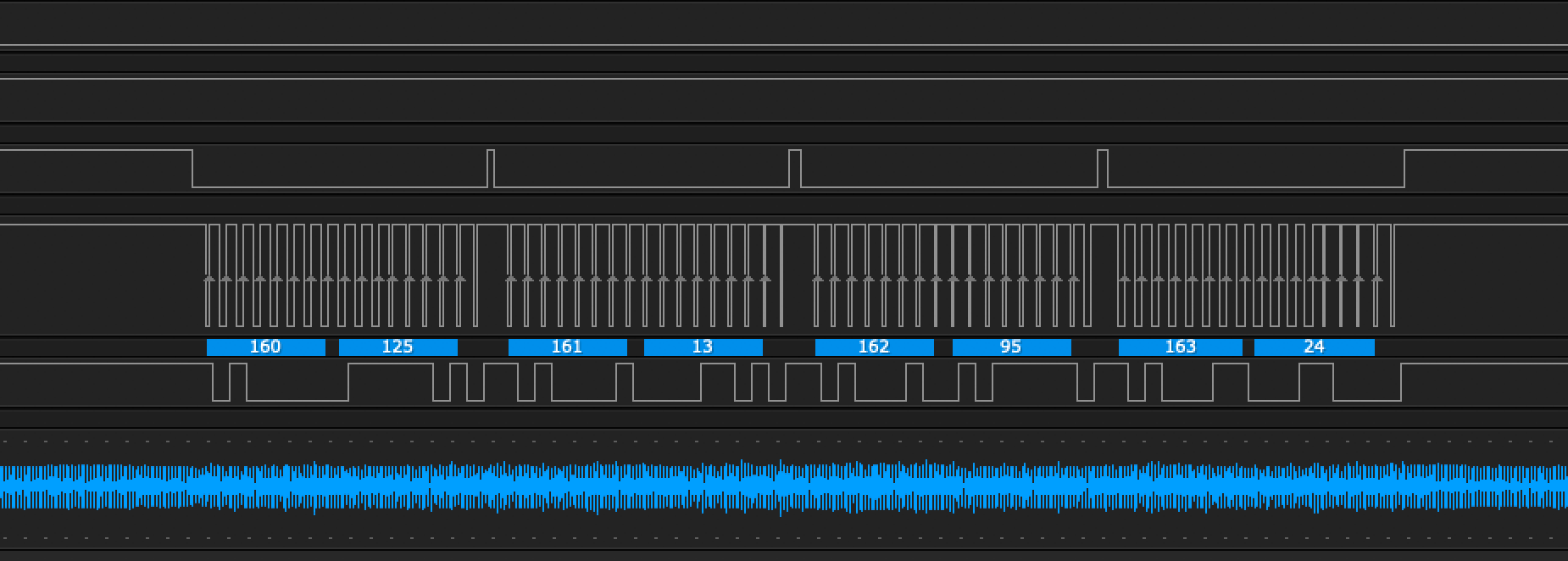
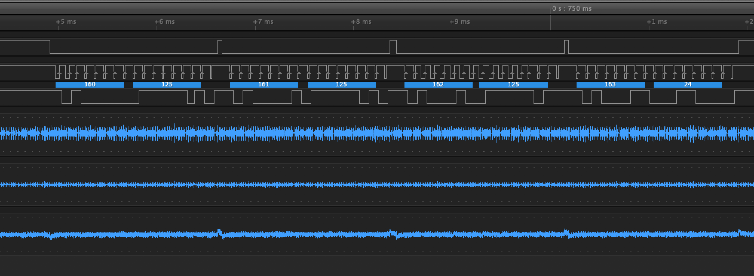
By inspection of these waveforms, it became pretty clear that for the Thousands, Hundreds, and Tens digits, 1 bit of the serial transmission is assigned to each segment of the digits (A,B,C, etc). The Ones digit is either zero or off. The rest of the bits which would be used to configure the Ones digit are used to control the flags "FORWARD", "REVERSE", "STOP", and "TAPPING". For now I've configure the "FORWARD" flag to turn on anytime the tachometer reads non-zero.
Here is my first test run from 0000-9999 on the LCD:
If anyone else is trying to work with this LCD I have more detailed notes. You can also get some clues by looking at the code on Github.
Mounting:
The SX3 comes with an electrical depth gauge. This gauge fits between the PCB of the button board and the front housing of the mill. I kept all of the components on the back of the board so that there would be sufficient clearance for the DRO.
If you have trouble getting the front cover off of your mill, you need to rotate the quill so to the fullest extend possible.
Next steps:
I still haven't decided how I want to mount the IR sensor for the tachometer. I am considering adding it to the top of the mill, but I'd like to see if it is possible to mount it internally for further protection and less mess.
I also need to assign functions to the seven buttons and create some labels to attach to the front of the mill.
The code for this project is available on Github here.
The board file and schematic (created using Eagle) are available on Github here. The board uses almost entirely surface-mount parts and some of them have a fine pitch, so buyer beware if you aren't comfortable with that level of soldering.