Home Antenna Grounding
I recently installed an end-fed wire antenna running from the apex of my garage into a large maple tree in my backyard. I want to get the best performance I can from the antenna and also take the appropriate precautions to operate safely and protect my equipment.
Most of my ham radio activity has been QRP/remote. I have not had an antenna continually installed at my house and have not taken the time to setup a proper ground system. I recently installed an end-fed wire antenna running from the apex of my garage into a large maple tree in my backyard. I want to get the best performance I can from the antenna and also take the appropriate precautions to operate safely and protect my equipment.
There is a lot of information about how to setup a grounding system for radio. Here is a summary of some of the key points I've learned about setting up a ground system:
- Use a single-point ground inside of the home. I am using a sheet of copper (0.5mm thick) screwed into a wooden board.
- Electrically bond all "earthed" items outside of the home together using mechanical attachment methods. This system should be bonded to ground rods driven into the ground.
- Use Lightning arrestors on each coax line to shunt high voltages to ground.
Parts/Equipment:
- 1ft x 1ft 0.5mm thick copper sheet (for internal "single point" ground)
- 1/8" thick copper sheet – approx 2in x 8in. This was leftover from the loop antenna project.
- Copper braizing rod and torch
- Utility enclosure kit: https://www.dxengineering.com/parts/DXE-UE-2P
- Lightning arrestors: https://www.dxengineering.com/parts/ALF-ATT3G50UBHP. *** See note below!
- Solid-core 6 AWG copper wire from Home Depot
Build
Since my arrestors are chassis-mount I want to connect them to ground plane with a minimal amount of resistance and plenty of current-carrying capacity.
First, cutting a couple of small strips of copper. I used a band saw for this:

I then cut holes into them and added a bend:

I drilled some holes and used M3 bolts to hold these brackets onto a 2" wide 1/8" thick sheet of copper ground plane. These bolts helped hold the copper securely as I brazed them into place:


Close up of the connection after some cleanup with a wire brush:

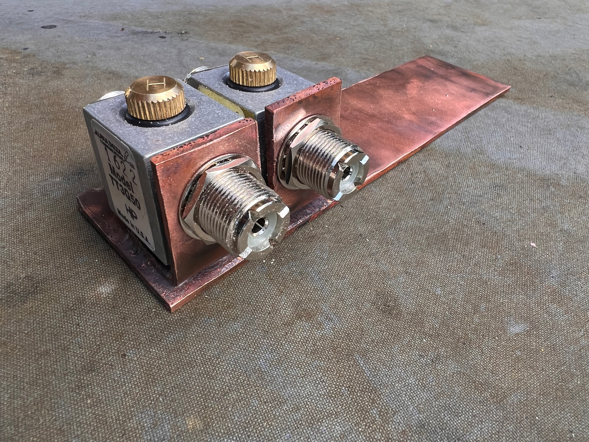
Arrestors installed onto bracket after some additional cleanup:

And the whole setup installed in the utility box on the exterior of the house near my workbench

Inside of the house, I have a single point ground installed with my coax selector switches mounted to it:

Results:
Its been nice having an antenna installed at home and its very convenient to not have to run coax out the back door every time I want to run a test. I don't think my end-fed installation is optimal by any stretch, but its a massive improvement over no antenna at all! It will be interesting to compare the results to my loop antenna.
A couple of nights after installing the antenna I saw a lot of activity on both 20m and 40m. Here is a portion of the 20m band that night (2022/05/18).
