DDS RF Signal Source
In 2017 I designed a local oscillator board which can be used to generate an RF signal in the HF range (< 30MHz).
I hope that this can become the building block for a more complete radio design, so I included a lot of expansion options including an I2S interface, I2C, SPI, tons of LEDS, 6-digit display, buttons, and FFC connectors to attach a rotary encoder board. I also used a power mcu which is capable of some serious audio filtering if I should choose to do that.
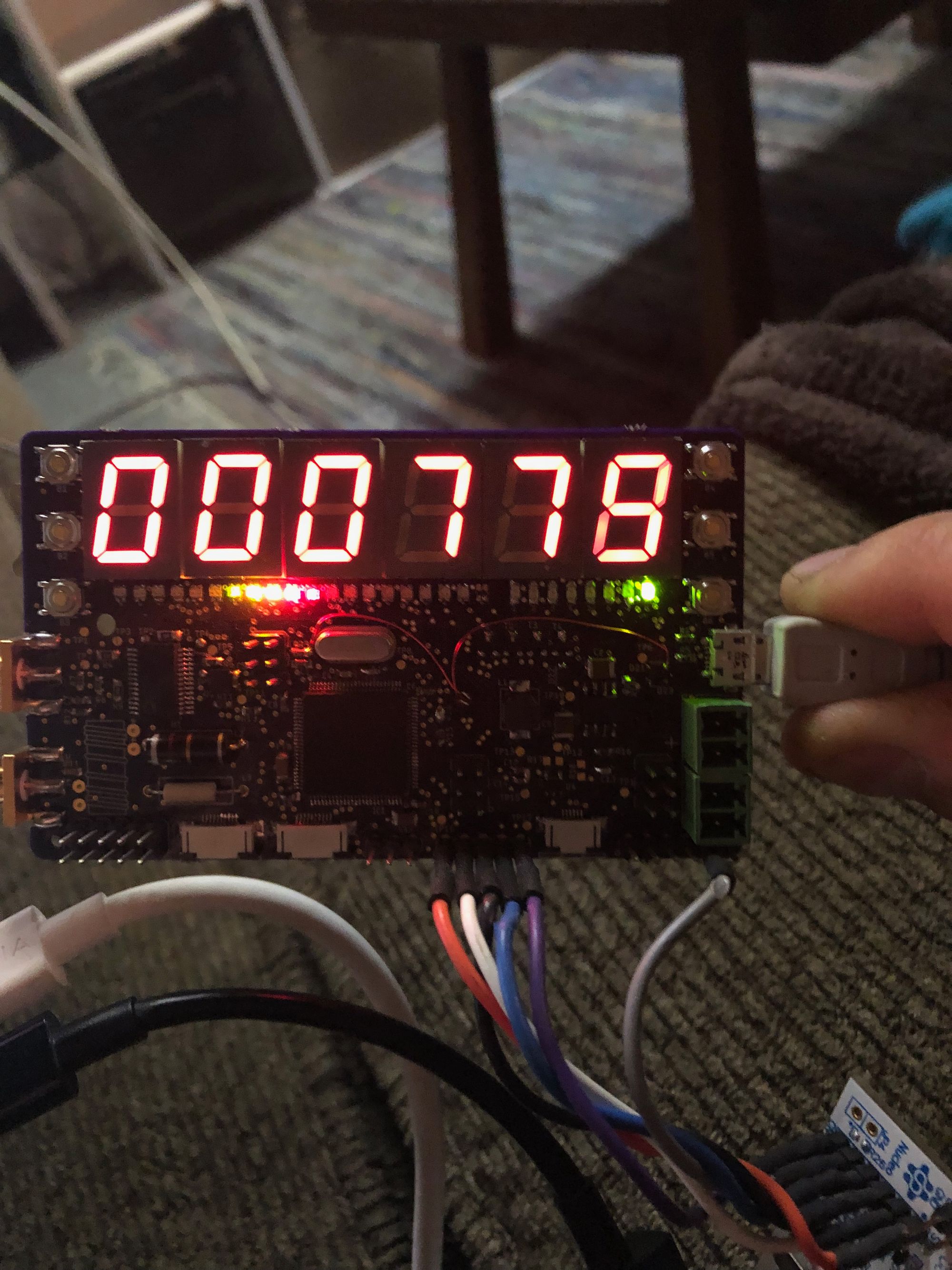
The assembled board looks like this:

Features:
- DC->30MHz programmable output (with a software config option this can be limited to ham bands and frequencies) including an active analog LPF with to reduce high order products.
- RF input for frequency counter measurements
- Regulated 3v3 (switcher + LDO) supply for mcu and peripherals
- Breakouts for two i2S interfaces
- 5 exposed GPIO's
- Breakout for UART interface
- Breakout for I2C interface
- (20) red/green LEDs
I intend to spend more time on this project soon and will post more information about it when I do.
The source code (still in progress!) is available here: https://github.com/esoren/FH_DDS
I have kept the PCB repository private for now until I finish fixing a couple of known bugs. If you have interest, send me an email and I can get it to you orr discuss further.
Here you can see the oscillator programmed to ramp from 7Mhz to 14Mhz. At this point, the output transistor wasn't correctly biased and you can see the sine wave output is a little distorted. I have fixed this in the current implementation.