Building the Control Board
This pages summarizes the bill-of-materials and schematic for the coffee roasting controller. Wiring up the controller is pretty straightforward and follows directly from the schematic.
Back to Modifying the Air Popper.
This pages summarizes the bill-of-materials and schematic for the coffee roasting controller. Wiring up the controller is pretty straightforward and follows directly from the schematic. Many of the components can be swapped out for components with similar functionality. For instance, likely any Arduino can be used with some minor modification to firmware. Similarly, the motor driver, SSR, and power supplies can all be interchanged for components with similar specs.
The hardware has the following requirements:
Hardware Requirements:
- Able to adjust the heater output (1200W+)
- Able to adjust the fan speed, 0-24V @ up to 2.5A
- Monitor the onboard temperature, chamber temperature, and ambient temperature
- User interface to let the user adjust the set points and view temperatures over time – touch screen preferred.
I settled on the following components to meet the goals. I selected some components (like the Arduino Uno and Nextion display) because I had them laying around from previous projects and didn't want to purchase something new.
BOM:
- Arduino Uno
- Nextion NX3224K028_011 touchscreen display (320x240 px)
- L298N motor driver (most push-pull drivers will work)
- 24V power supply - 3A+
- 5V power supply - for Logic
- Adafruit MCP9600 breakout board w/ type K thermocouple (I2C)
- IEC terminal + fuse
- SSR-10DA solid state relay (I had this already – I would opt for a 25A relay if I bought a new one for this project).
- Small 24V fan for cooling the L298N directly connected to the output of the 24V fan.
I attached all of the components to a piece of plywood and wired them up according to the following schematic:

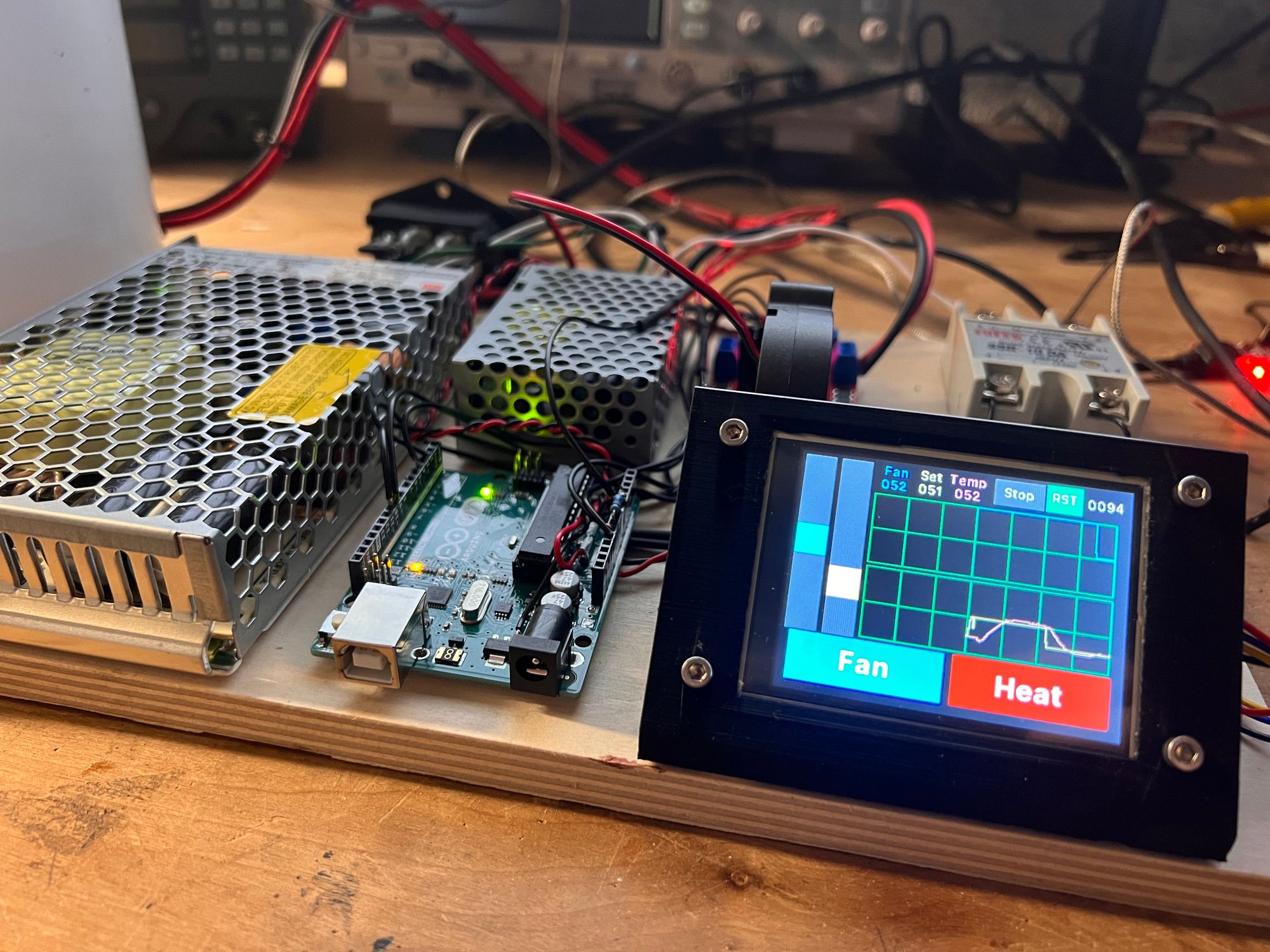
Here is a picture of the assembled control board with each of the components labelled:

A note on programming:
The Nextion display uses the only serial port on the Arduino Uno. This introduces two complications:
- The Nextion display must be unplugged from the Arduino before the arduino can be programmed using the built-in bootloader.
- The Nextion display must be detached from the Arduino and programmed separately using a USB->Serial programmer.
Both of those issues could be resolved using a more capable Arduino like the Arduino Mega. If I were to start the project over from scratch I'd likely take this approach to make development less cumbersome.
Continue to User Interface and Firmware